1.
Shift the motor into reverse, you will have to spin the prop by
hand, DO NOT FORCE THE SHIFTER!
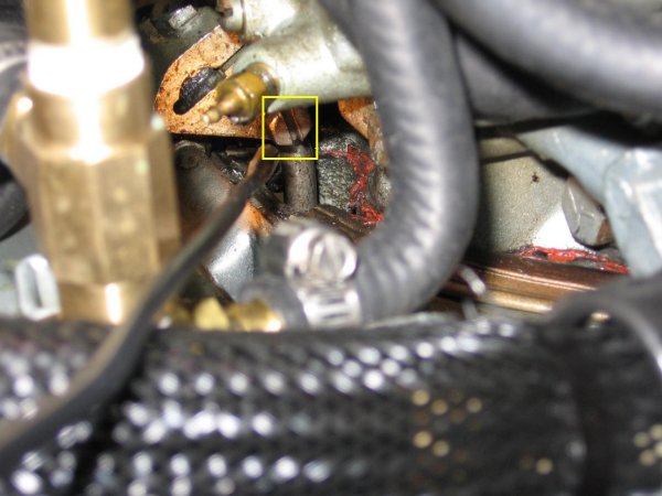
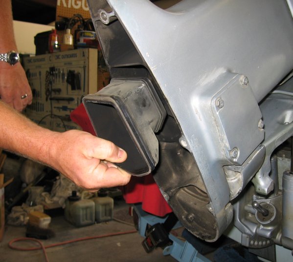
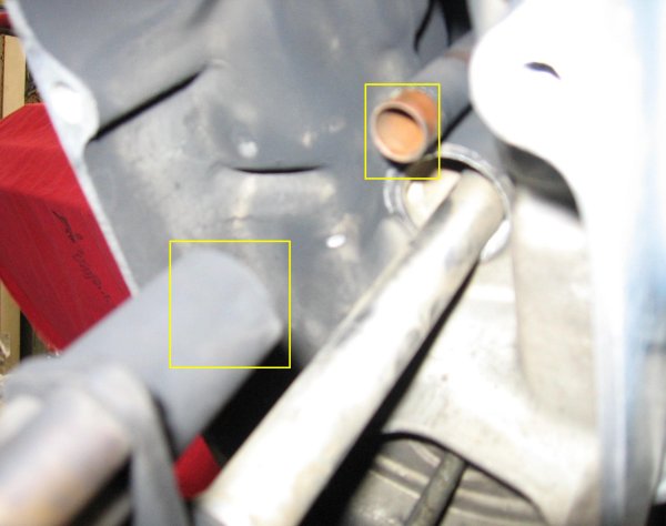
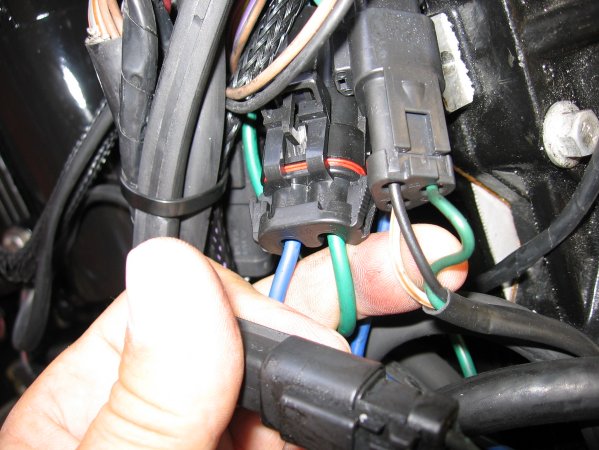
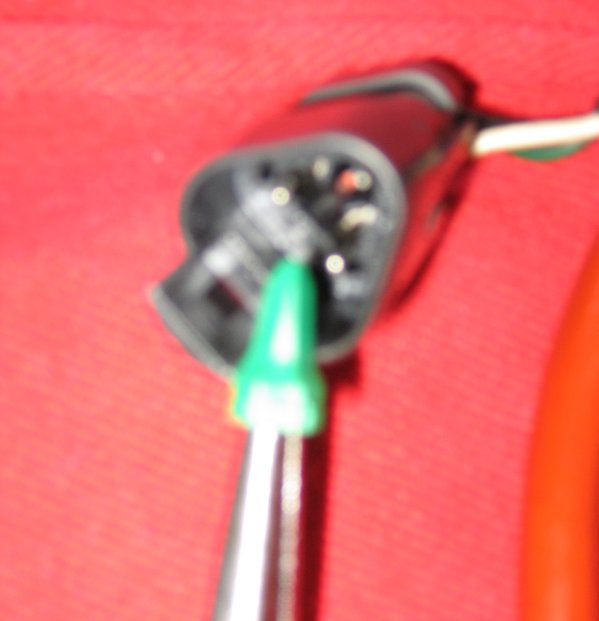
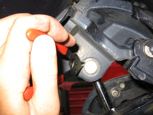
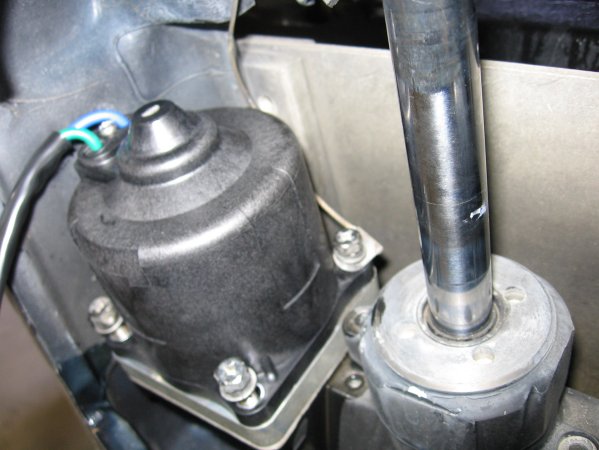
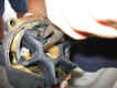
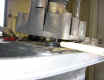
You need to remove the shifter pin, it is located
below the carburetors in the front of the intake. It is
hard to see on some motors but if you look in from the left side
you should be able to see it.
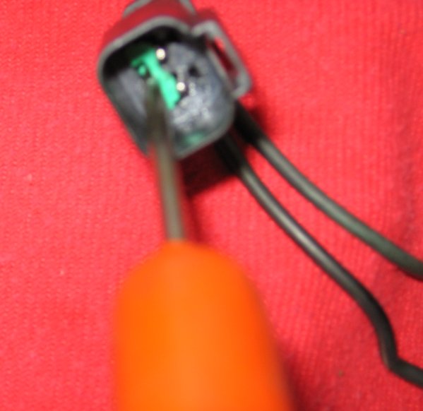
A 1/4 inch drive ratchet, long extension, swivel
and 3/8 inch socket will aid in the removal. |
 |
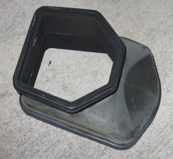
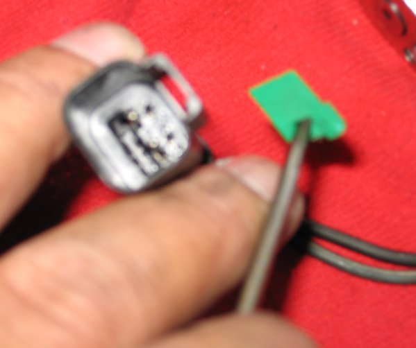
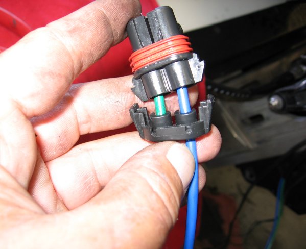
The
air box has been removed on this motor to get a better
picture. |
|
 |
 |
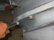 |
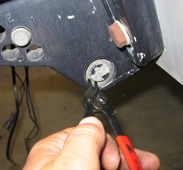
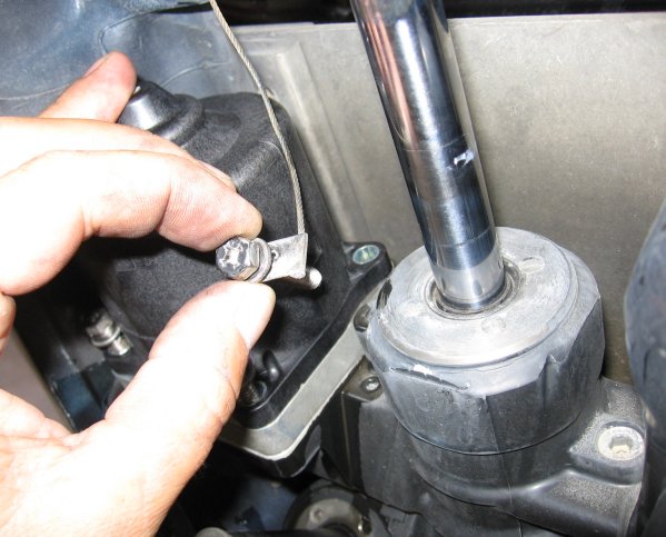
2.
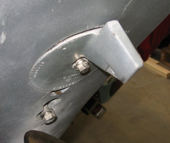
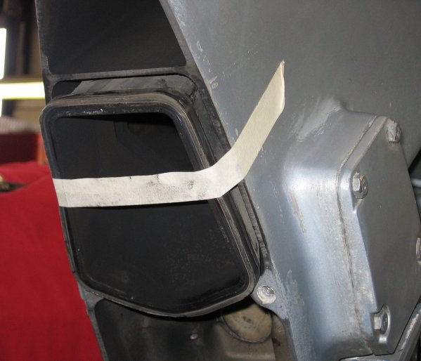
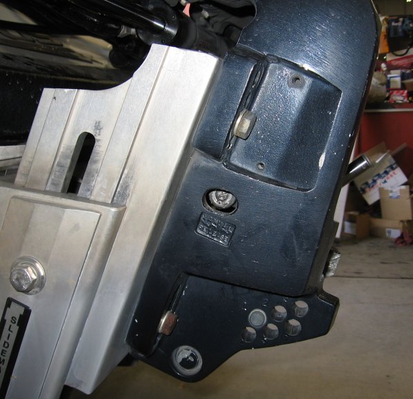
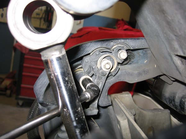
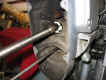
Once you have the shifter pin out, trim the motor up to
full tilt and remove the torque tab, the two bolts below
the cavitation plate and the four bolts on the side of the
gearcase. |
|
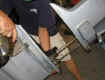 |
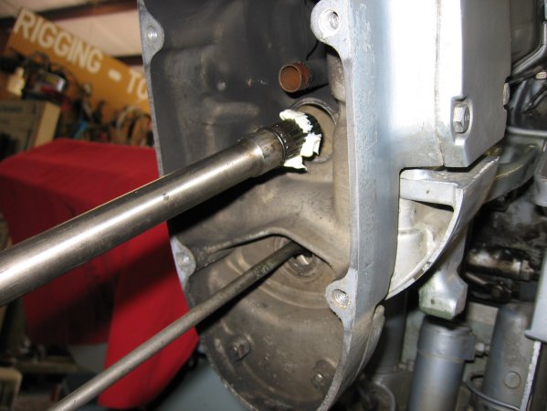
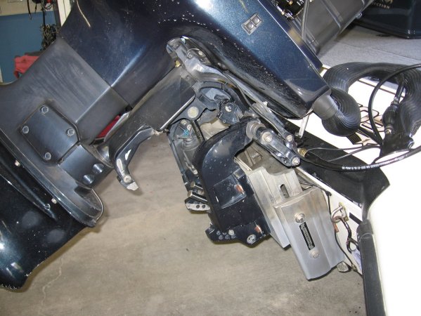
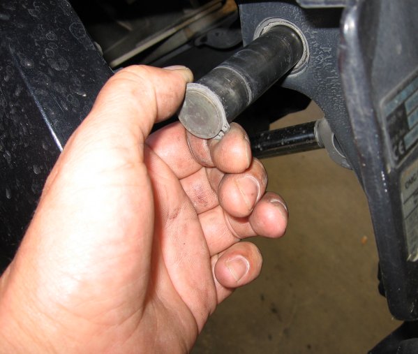
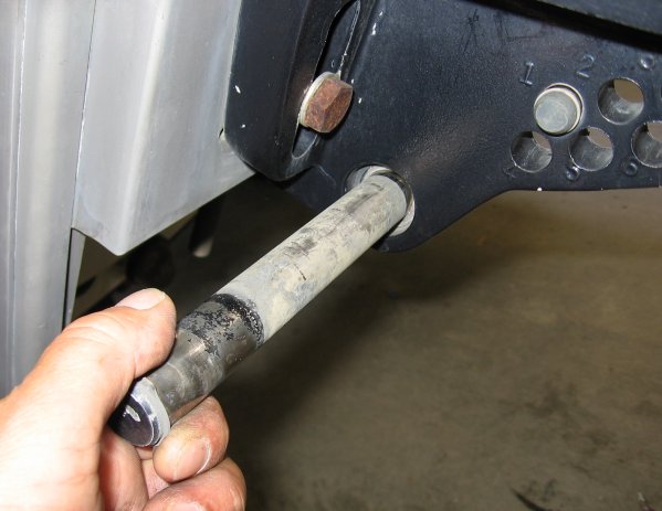
3.
Remove the gear case. |
|
 |
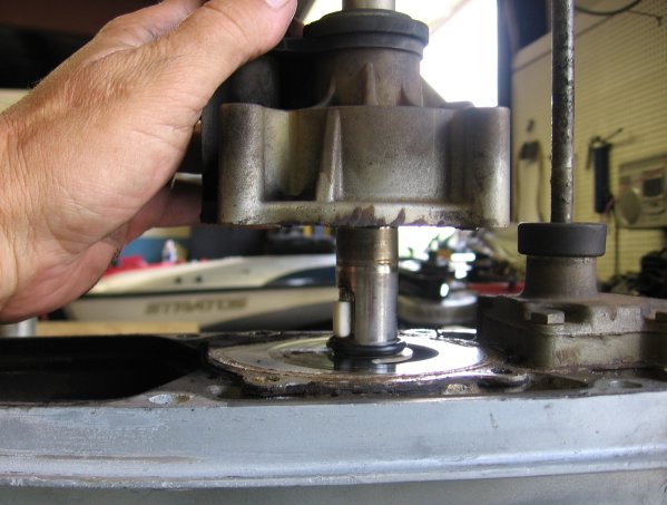
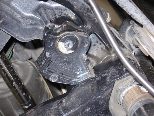
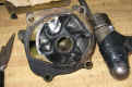
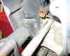
4.
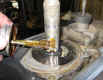
This is the water pump housing; remove
the four bolts from the housing. |
|
|

|
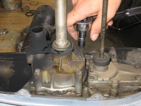
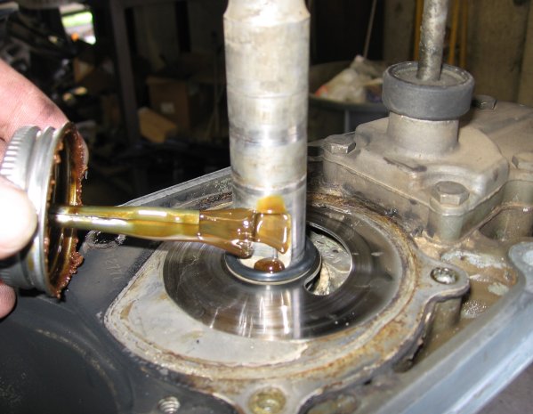
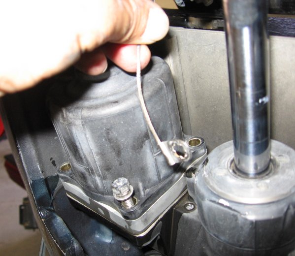
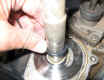
5.
On some models there is an O-ring at the top of the drive
shaft, remove it if yours is equipped then remove the
water pump housing. |
|
|

|
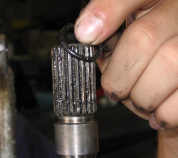
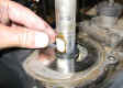
6.
This model has the metal impeller key, on most models this
key is no
longer used, this is only true if the drive shaft has the
flat keyway in the
drive shaft. |
|
|
|
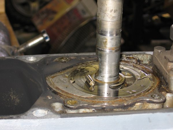
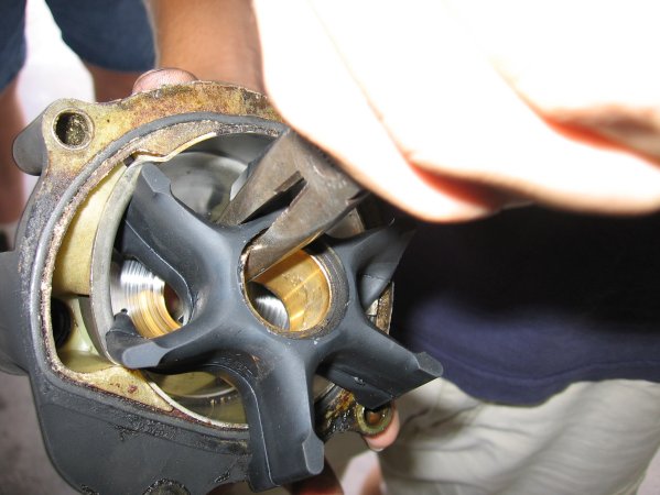
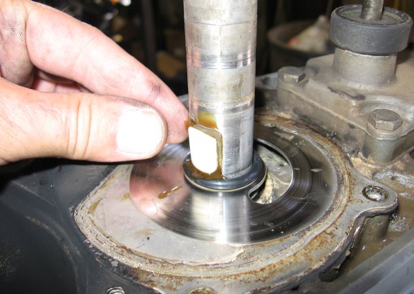
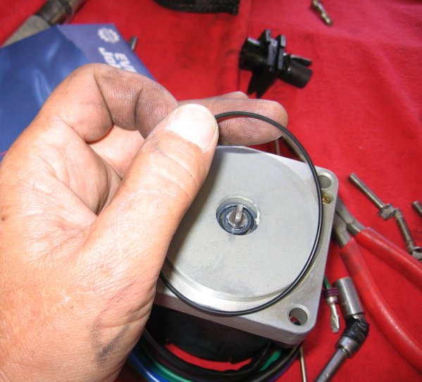
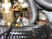
7.
Notice that the impeller is in the housing with a
counter-clockwise twist, this is important when you
install the new impeller as it must be
installed this way. |
|
|

|
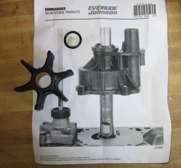
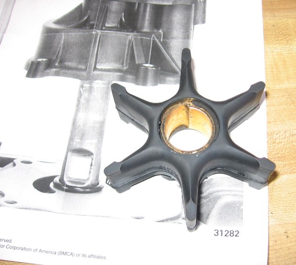
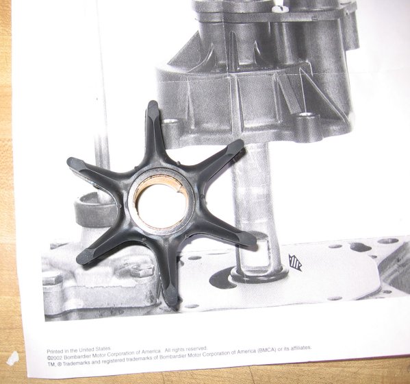
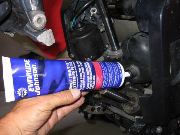
8.
This is the replacement impeller kit and its contents; it
also includes the instructions on how to install the new
plastic impeller key, o-ring and impeller. |
|
 |
 |
9.
The impeller will only fit one way, make sure you get the
open side down. |
|
|
|
10.
Hold the impeller with a pair of pliers and rotate it into
the impeller housing with a counter-clockwise motion, I
like to align the impeller key opening to the back of the
housing to aid with the installation of the key. |
|
|
|
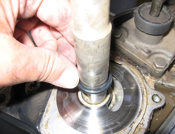
11.
Install the impeller o-ring on the drive shaft and slide
it down to the water pump plate. |
|
|
|
 |
12.
Apply some grease or other compound to hold the key to the
shaft while installing the water pump housing; make sure
the key is positioned correctly. |
|
|

|
|
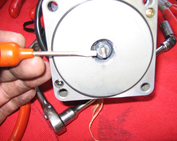
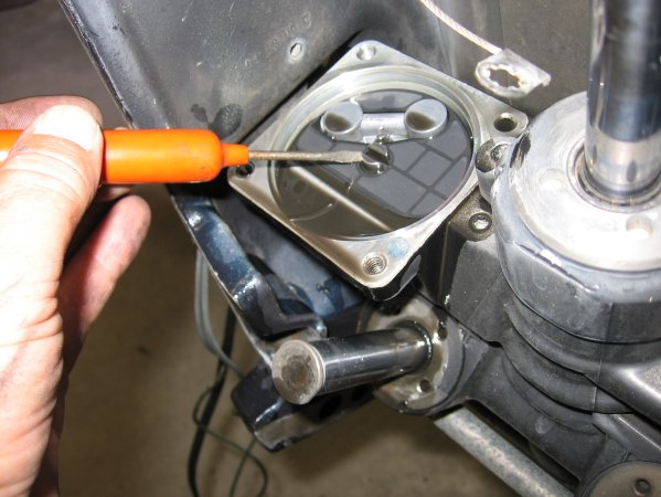
13.
Slide the housing down the drive shaft and use a small
screwdriver to hold the key while installing the housing. |
|
|

|
14.
Reinstall the housing bolts. |
|
|

|
15.
Reinstall the top drive shaft O-ring (if equipped). |
|
|
|
| 17.
Move the boat shift handle to Forward gear. |
| 18.
Push down on the gear case shift rod and turn the propeller to
shift the gear case into reverse gear. |
 |
19.
Apply a small amount of BRP Moly lube to the drive shaft
splines and slide gear case back into the midsection. |
|
| |
 |
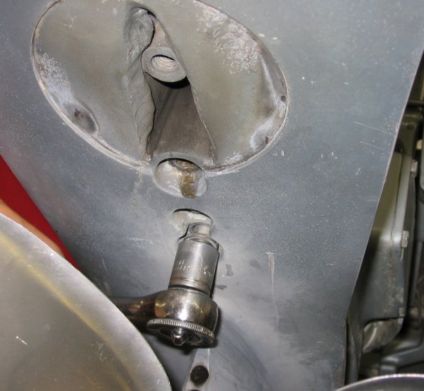
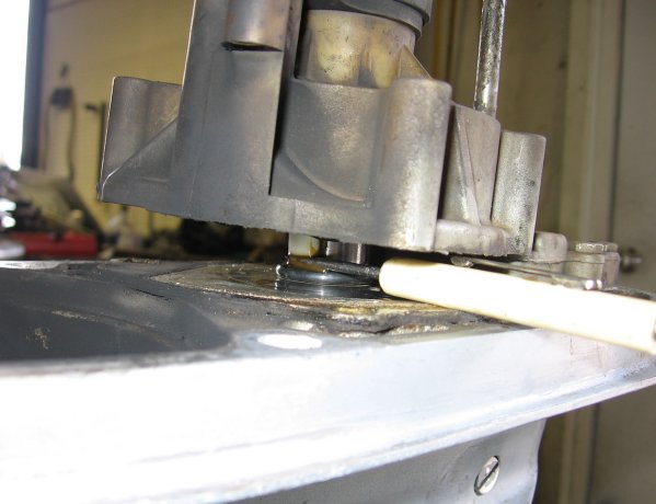
**
Caution!! The water tube MUST be aligned in the
water pump housing.
Failure to align the water tube can cause damage to
the water tube, water pump housing and will
cause the motor to run hot, resulting in power head
damage. |
|
| 20.
As you slide the gear case on you will have to spin the
propeller to engage the crankshaft splines. |
|

|
 |
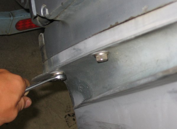
21.
Reinstall the gear case bolts and tighten securely. |
|
 |
22.
Reinstall the shifter bolt, this may take two people and
some time, when the bolt is installed correctly the shift
handle will operate as normal, if not correctly installed
the gear case will not shift.
The shifter bolt must be inserted through the hole in the
shift rod. |
|
| 23. Reinstall plug
wires, attach kill switch lanyard, attach water hose and start
motor to verify water flow from water pump and shifting. |
| **
Caution!! Spinning propellers are a Safety Hazard that
can cause injury. |
|
I
would like to Thank Dwayne and Jason for their help with this......John. |
|

|